
Gyro / Acceleration Sensor Board helps balancing KTX walking and acrobatic motions.
The kit comes with sensor board and cable, screws.
- Sensor board x1
- IX-Bus Cable x 1
- M2-4 Non-Tapping Screw x 4
Installation
Tools:
- Phillips-head screw driver P.1
- Phillips-head screw driver P.0 or P.00
* For M2 screws, I normally use P.00 screw drivers; however, the head size varies a little by the make, chose best fitting screw driver to prevent damaging the screw head.
- Loctite
* Apply a little to the screw thread when the screw is screwed into threaded metal parts.
Step1: Take off the body plates and ...
Using P.1 screw driver,Take off the front and back body plate off. There are 4 screws on both front and back. If you have remote receiver connected, take it off. Also, take off the battery, too.
Step2: Take off the sensor bracket and left arm.


Take off the sensor bracket. There are 2 screws on both front and back.
Step3: Connect cable to the sensor board

Connect IX-Bus cable to the sensor board. Make sure the orientation of the cable is correct. You should have brown cable connected to pin #1 as shown in above picture. Also, make sure the dip switch is set to all OFF. For more information, please look at setup document here.
Step4: Place sensor board on the bracket

Run the cable through the hole of the bracket as shown in the picture.


Using P.00 (or P.0) screw driver, screw the sensor board on the bracket with 4 M2-4 non-tapping screws. Don't forget Loctite!!!
Step5: Place the sensor bracket back on the robot
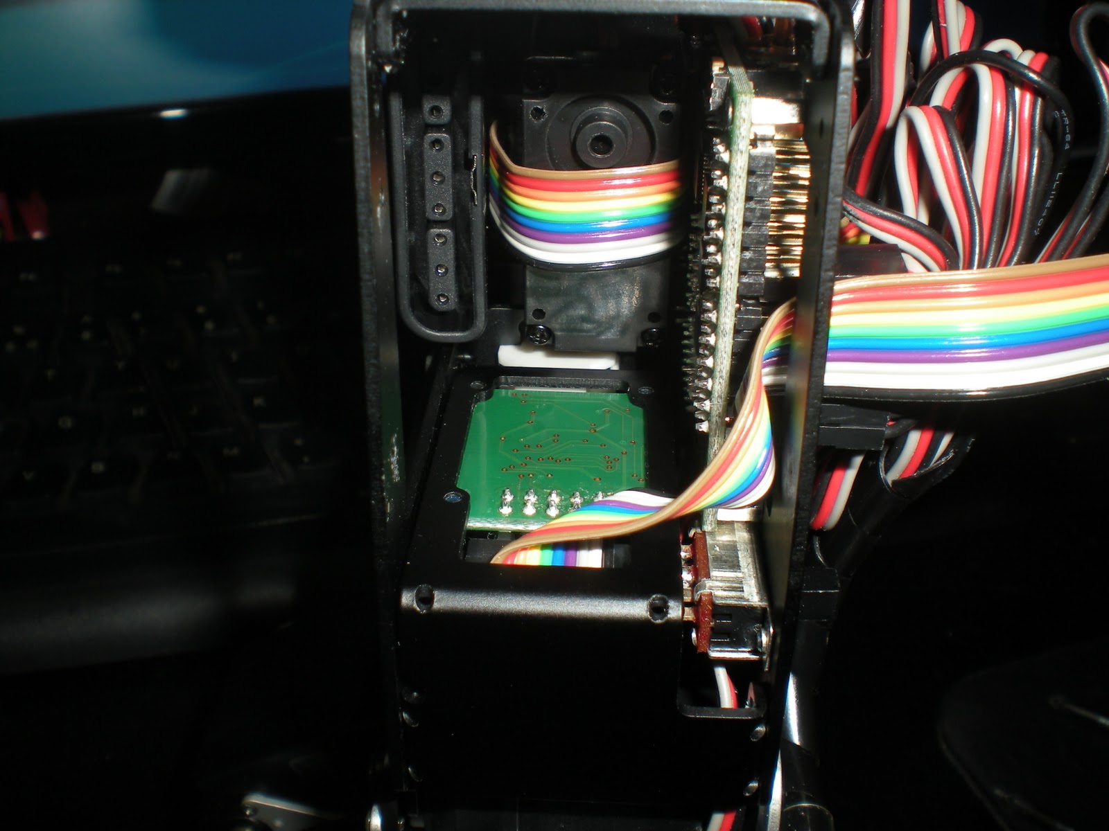

Take off 4 M2-4 screws that holding the CPU board and slid the board to the right.
Run the IX-Bus cable through the space between the CPU board and the back side metal plate.
Mount the sensor board bracket. Screw 2 M2-4 on both front and back.
Step6: Place the left arm


Step7: Connect the servo cables of left arm


Step8: Connect IX-Bus cable to the CPU board
 Connect the IX-Bus cable to the CPU board.
Step9: Put everything back
Put everything back on the robot such as remote receiver, body plates, and battery.
* I normally leave the battery unplugged, so that it won't runs out the charge.
Step10: Setting up the board using RM2
Go to this link and open or download PDF file, and follow the instruction!!!